Schedule 10
Conditions to be met for a culvert with a conduit having outlets where the conditions provided for in Schedule 9 for the layout of a culvert with a round conduit may not be met
![]()
1
Explanations
The outlets create a series of thresholds and basins in the culvert so that the water speed and depth are sufficient to ensure the free flow of fish.
All the conditions indicated in Schedule 10 must be complied with when installing a culvert with outlets. If it is not possible to comply with a given condition (e.g. if it is difficult to comply with burial conditions due to the presence of rock), another type of structure (arch, bridge, etc.) must be installed instead.
Additional information
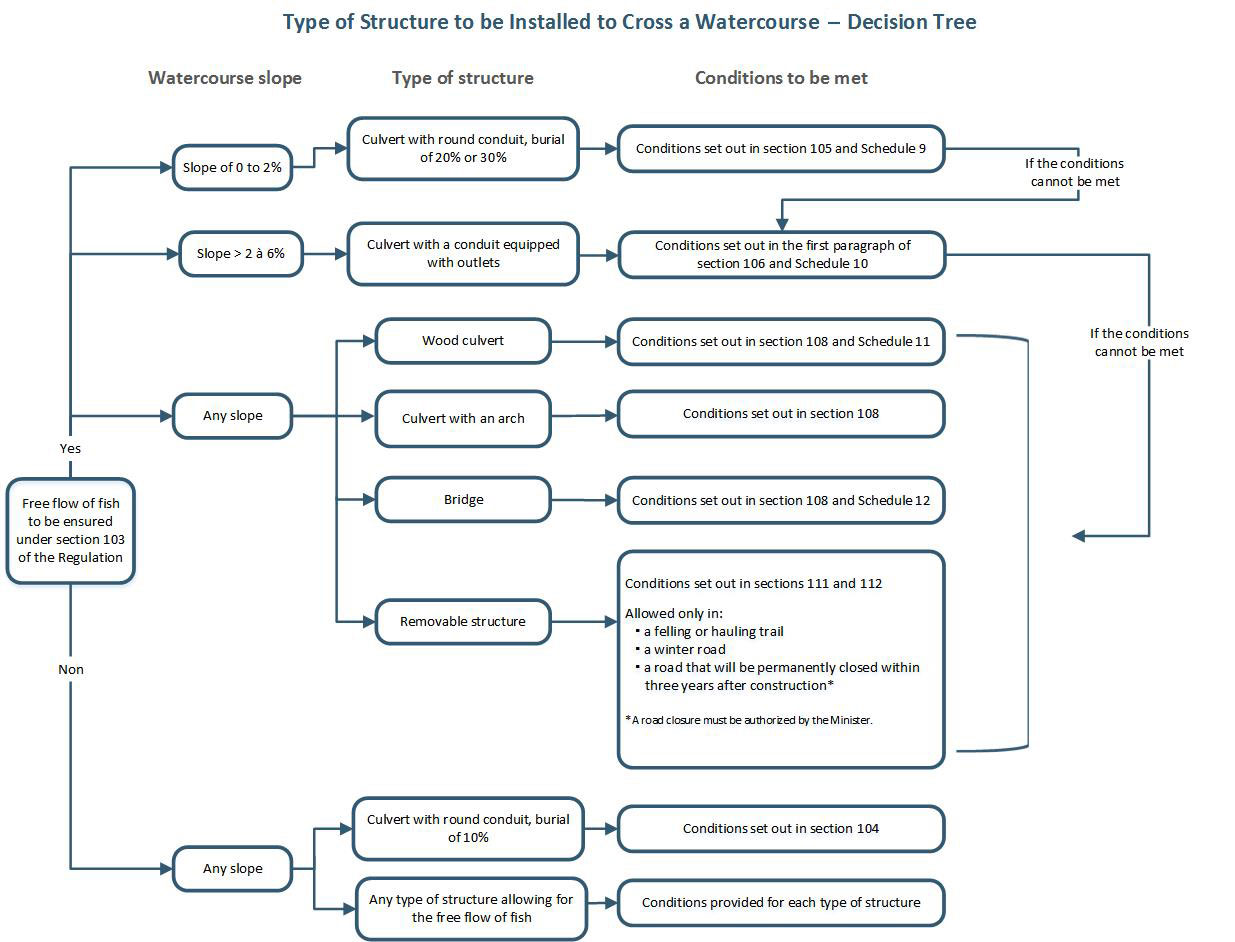
The decision tree below can be used to decide on the type of structure that must be installed to cross a watercourse.
Slope of watercourse
Conduits with outlets must be installed in watercourses whose slope is greater than 2%. In addition, the slope of the watercourse may not exceed the percentage appearing in table 1, which varies on the basis of the length of the conduits.
![]()
2
Additional information
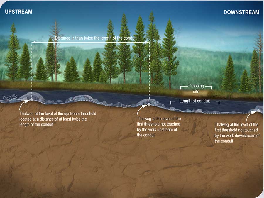
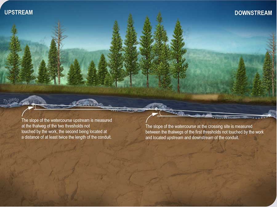
The slope of a watercourse is measured between two natural thresholds unaffected by the work (excavation, conduit installation, riprap, etc.). A threshold is an elevation of substrate across a watercourse that is not necessarily perpendicular to its axis and that is situated between the two deepest sections.
In a watercourse with a standard profile (no thresholds, channels or rapids), the slope may be measured from arbitrary points on the watercourse thalweg.
The slope of a watercourse must be assessed using a device that is sufficiently accurate. For example, a preliminary estimate may be made using a clinometer, but more accurate instruments, such as a precision sight level or an integrated set of measuring instruments that automatically measure both angles and distances during a land survey, are needed at the culvert installation stage.
The preliminary estimate of the slope of the watercourse when marking the course could help guide the initial selection of the type of structure suitable for the watercourse to be crossed. However, before the final choice of structure type, the slope of the river must be validated with specific instruments. For a conduit with outlets, the validation must demonstrate that the measured slope does not actually exceed 5% or 6%, depending on the length of the conduit. If the validation is inconclusive, the initially-planned choice of a conduit with outlets must be modified to a type of structure adapted to the watercourse to ensure a successful free flow of fish.
Some situations increase the uncertainty associated with the use of a slope estimate at the preliminary stages of the project and therefore the risk of having to change the type of structure at the end of the project. These situations must be considered by the proponent as, regardless of the method used, he or she remains responsible for compliance with all of the Regulation’s conditions.
In more uncertain situations, it may be advantageous to immediately select a type of culvert that will comply with the Regulation regardless of the slope of the watercourse and the length of the structure (wood culvert, arch culvert, bridge, etc.). This is especially important because the substrates of watercourses with a steep slope are generally coarser, which can lead to excavation difficulties and even compromise the proper burial of a conduit with outlets, which is an essential condition to ensure the free flow of fish. Coarse substrates may, however, be an advantage to the stability of other types of structure.
Figure Schedule 9A Placement of thresholds used to measure the slope of a watercourse
Figure Schedule 9B Measuring the slope of a watercourse
Narrowing and widening of the watercourse
Maximum narrowing of the width of the watercourse: 20%
Widening of the watercourse: where required by the calculation of the flow![]()
3
Additional information
How is the width of a watercourse measured?The width of a watercourse is calculated using the average of at least four representative measurements of the natural watercourse taken upstream and downstream of the crossing site. If there are signs of narrowing or widening, the section in question (e.g. area disturbed by a beaver dam) must be excluded. The width is measured at the level of the upper limit of the banks. The method used to identify the upper limit is shown in the definition of “bank”.
The distance between the conduits of a culvert with parallel conduits must be considered when calculating the narrowing of the natural width of the watercourse by the culvert. The minimum distance between the conduits is one metre, as specified in section 102 of this Regulation.
Dimensions of conduits
Minimum diameter of the conduits: 1,200 mm
Minimum length of the conduits: 9 m
Maximum length of the conduits: 24 m
Design of outlets
Characteristics of outlets
The outlets must be manufactured to remain in good working order and be functional for the expected life of the conduit. The outlets must not reduce the expected life of the conduit.
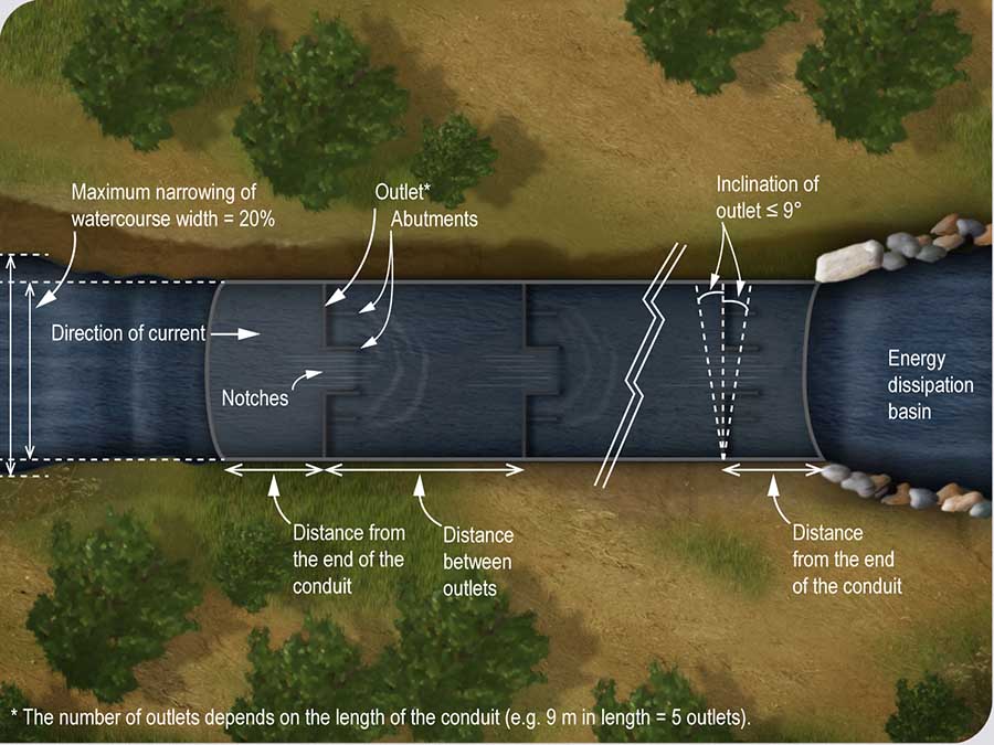
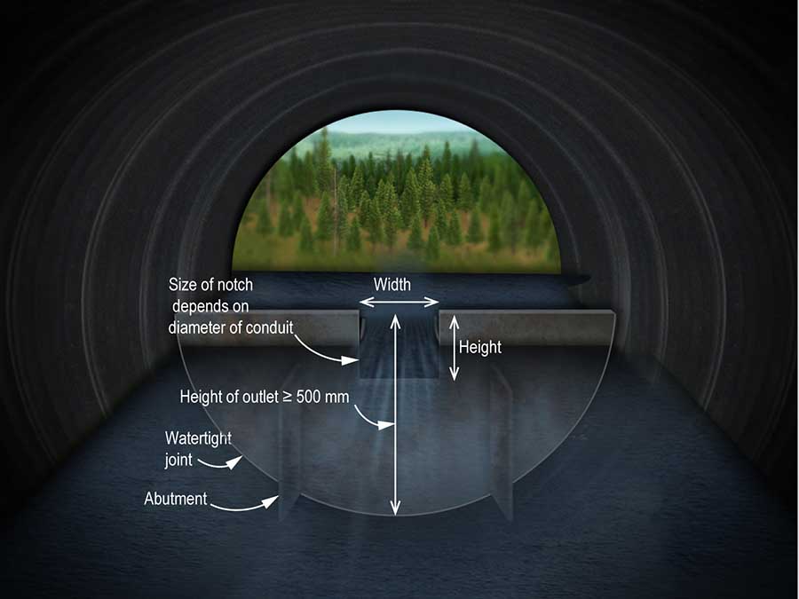
The outlets must have a height of 500 mm or more and dull edges. They must be equipped with abutments. The material of the outlets must be corrosion resistant.
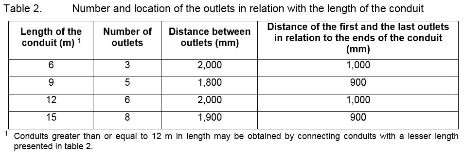
The outlets must not be inclined by more than 9 degrees in relation with the transverse axis of the conduit. The joints between the outlets and the conduit must be leakproof. The number of outlets and their location in the conduits must comply with the standards in table 2, which vary according to the length of the conduit.
![]()
4
Additional information
Outlet materials must be corrosion-resistant. For example, the welded joints must be galvanized to prevent rusting.
Figure Schedule 10A Location of outlets in a conduit
Characteristics of notches in outlets
Notches in outlets must be rectangular with dull edges. Notches may be located in the centre of the outlets or off-centre alternating from one outlet to the other. The dimensions of the notches in the outlets must comply with the standards in table 3, which vary according to the diameter of the conduit.
![]()
Procedure for installation
Burial depth of downstream invert ![]()
6
Additional information
The elevation of the thalweg and the invert of conduits with outlets must be measured with accurate instruments (precision sight level, an integrated set of measuring instruments that automatically measure both angles and distances during a land survey, etc.).
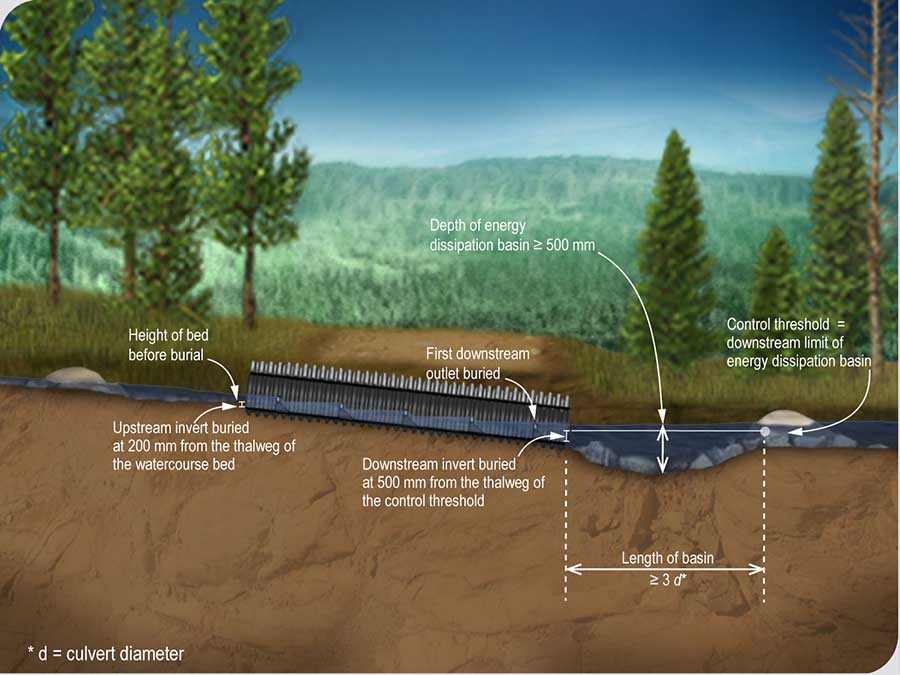
Figure Schedule 10C Burial depth of a conduit equipped with outlets compared to the thalweg and characteristics of the energy dissipation basin
The downstream invert of the conduit must be buried at a depth of 500 mm in relation with the thalweg of the control sill not touched by the work. The control sill is located downstream of the energy dissipation basin at a distance equal to or greater than three times the diameter of the conduit. The first outlet downstream of the culvert will be submerged.
Burial depth of the upstream invert![]()
7
Additional information
The elevation of the thalweg and the invert of conduits with outlets must be measured with accurate instruments (precision sight level, an integrated set of measuring instruments that automatically measure both angles and distances during a land survey, etc.).
Figure Schedule 10C Burial depth of a conduit equipped with outlets compared to the thalweg and characteristics of the energy dissipation basin
The upstream invert of the conduit must be buried at a depth of 200 mm in relation with the thalweg of the bed of the watercourse before the installation.
Energy dissipation basin
An energy dissipation basin is required downstream of the conduit. The downstream limit of the energy dissipation basin must be the control sill not touched by the work located at a distance equal to or greater than three times the diameter of the conduit. The depth of the energy dissipation basin must be ≥ 500 mm.![]()
8
Additional information
The energy dissipation basin absorbs the energy and turbulence of the water leaving the culvert and provides a rest area for fish. If there is no natural basin downstream of the conduit, one must be created by excavating the watercourse bed. The bottom and sides of the basin must be stable, to avoid scouring. Where necessary, they must be stabilized with riprap. The geotextile membrane must be placed on the sides of the basin, anchored under the riprap, not under the riprap at the bottom of the basin. The space occupied by the riprap must therefore be considered when digging the energy dissipation basin, so as not to reduce its volume. The control threshold at the basin exit must not be altered by the work.
Figure Schedule 10C Burial depth of a conduit equipped with outlets compared to the thalweg and characteristics of the energy dissipation basin
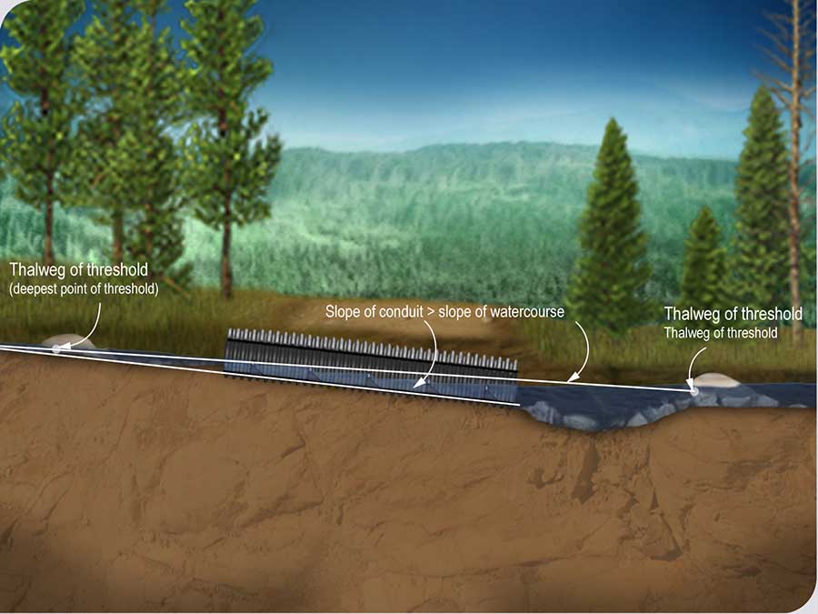
Slope for the installation of the conduit
The slope for the installation of the conduit depends on the slope of the watercourse, the length of the conduit and the burial depth of the upstream and downstream inverts. The installation slope must therefore be greater than the slope of the watercourse.![]()
Culvert with parallel conduits
If outlets are installed in both conduits, the inverts of the conduits must be buried at the same depth.
If outlets are installed in only one conduit, the invert of the conduit without outlet must be located 500 mm higher than the invert of the conduit with outlets.![]()
10
Additional information
If the conduit with no outlets is placed higher than the conduit with outlets, the water is concentrated in the conduit with outlets during low flow periods. This ensures an adequate water level in the conduit with outlets. The outlets create a series of thresholds and basins in the culvert to maintain a fast enough flow and sufficient depth of water to ensure the free flow of fish.
Prohibited practices
The following practices are prohibited:
- on-site welding;
- torch cutting of steel elements;
- cutting holes with a torch.


